Tuesday, December 15, 2015

Smaug - Application Data Protection for OpenStack


During the recent OpenStack Tokyo 2015 summit, we introduced a new project that we've been working on recently, which will provide an Application Data Protection as a Service (video) (slides).

What is Smaug?

Not to be confused with Application Security or DLP, Smaug deals with protecting the Data that comprises an OpenStack-deployed Application (what is referred to as "Project" in Keystone terminology) against loss/damage (e.g. backup, replication).
It does that by providing a standard framework of APIs and services that enables vendors to introduce various data protection services into a coherent and unified flow for the user.

We named it Smaug after the famous dragon from J.R.R. Tolkien’s “The Hobbit”, which was known to guard the treasures of the kingdom of Erebor, as well as have specific knowledge on every item in its hoard.  Unlike its namesake, our Smaug is designed to give a simple and user-friendly experience, and not burn a user to a crisp when they want to recover a protected item.

The main concept behind Smaug is to provide protection of an entire OpenStack project, across OpenStack sites (or with a single local site).

Lets take a typical 3-tier cloud app:


In order to fully protect such a deployment (e.g. Disaster Recovery), we would have to protect many resources, which have some dependency between them.

The following diagram shows how such a dependency tree might look:


In Smaug, we defined a plugin engine that loads a protection plugin for each resource type.
Then, we let the user create a Protection Plan, which consists of all the resources she wants to protect.
   
These resources can be divided into groups, each of which is handled by a different plugin in Smaug:
  • Volume - Typically, a block of data that is mapped/attached to the VM and used for reading/writing
  • VM - A deployed workload unit, usually comprised of some metadata (configuration, preferences) and connected resources (dependencies)
  • Virtual Network - The virtual network overlay where the VM runs
  • Project - A group of VMs and their shared resources (e.g. networks, volumes, images, etc.)
  • Image - A software distribution package that is used to launch a VM

Smaug Highlights 

Open Architecture

Vendors create plugins that implement Protection mechanisms for different OpenStack resources.

User perspective: Protect Application Deployment

Users configure and manage custom protection plans on the deployed resources (topology, VMs, volumes, images, …).
The user selects a "Protection Provider" from a selection of available Protection Providers, which is maintained and managed by the admin.

Admin perspective: Configure Protection Providers  

The Admin defines which Protection Providers are available to the users.  
A "Protection Provider" is basically a bundle of per-resource protection plugins and a bank, which are curated from the total available protection plugins and bank plugins.
In addition, the Admin configures a Bank Account for each user (tenant).


Smaug APIs

We are currently in the process of defining Smaug's set of User Service APIs:


Resource (Protectable) API

Enables the Smaug user to access information about which resource types are protectable (i.e. can be protected by Smaug).
In addition, enables the user to get  additional information on each resource type, such as a list of actual instances and their dependencies.

Plan API

Enables the Smaug user to create or edit Protection Plans using a selected Protection Provider, as well as access all the parameters of the plan.

Provider API 

Enables the Smaug user to list available providers and get parameters and result schema super-set for all plugins of a specific Provider.

Checkpoints API

Enables the Smaug user to access and manage Protection Checkpoints, as well as listing and querying of the existing Checkpoints in a Provider.In addition, provides Checkpoint Read Access to the Restore API, when recovering a protected application's data.
Calling the Checkpoint Create (POST) API will start a protection process that will create a Vault in the user's Bank Account, on the Bank that is assigned to the Provider.
The process will then pass the Vault on a call to the Protect action on each of the Protection Plugins assigned to the Provider, so each will write its metadata into the Vault. 
It is left up to the Plugin implementation to decide where to store the actual data (i.e. in the Vault or somewhere else).

Schedule Operation API

Enables the Smaug user to create a mapping between a Trigger and Operation(s) definitions 

Smaug Architecture


We defined three services for Smaug:

Smaug API service

These top-level north-bound APIs expose Application Data Protection services to the Smaug user.
The purpose of the services is to maximize flexibility and accommodate for (hopefully) any kind of protection for any type of resource, whether it is a basic OpenStack resource (such as a VM, Volume, Image, etc.) or some ancillary resource within an application system that is not managed in OpenStack (such as a hardware device, an external database, etc.).

Smaug Schedule Service

This subsystem is responsible for scheduling and orchestrating the execution of Protection Plans.
The implementation can be replaced by any other external solution.
All actual Protection-related activities are managed via the Operation northbound APIs, in order to support:
  • Record maintaining of all operations in the Smaug database (to drive Operation Status APIs)
  • Decoupling the implementation of the Scheduler from the implementation of the Protection Service

Smaug Protection Service

This subsystem is responsible for handling the following tasks:
  • Operation Execution
  • protectable(resources) plugin management 
  • Protection provider management
  • Protection Plugin management
  • Bank Plugin management
  • Bank checkpoints sub-service

Join Smaug

We are currently in the process of reviewing the API definition
  • Our IRC (we are always there): #openstack-smaug 


Wednesday, October 14, 2015

Multi-Site Management in OpenStack

Managing multiple Openstack clouds as a single resource pool


In this series of posts, we would be diving into "Tricircle" 
- an open source project that promises to give a "single pane of glass" management over multiple OpenStack environments, using a cascading approach.

As more and more companies are deploying OpenStack, it is becoming clear that there is a need to be able to manage multiple cloud installations. The reasons range from application lifecycle management, through spill-over scenarios and all the way to multi-site Disaster Recovery orchestration.


So why would one care to deploy the same service over multiple environments?


There are multiple reasons, and here are a few:

  • Service continuity and geo-redundancy (in case of one site going awry)
  • Geo-based load balancing and service locality (in case traffic comes from various places in the globe, or if there are strict quality/latency requirements, or if there are regulatory constraints, etc)
  • Cost optimization (in case some resources are cheaper in another place)
  • Growth (in case one environment cannot grow enough)
  • Resource Utilization (in case you have multiple sites and want to aggregate their resources for better value or easier management)
  • Single Configuration (instead of continually synchronizing multiple sub-instances of the service)
  • ... (feel free to share additional incentives in the comments).

OpenStack Tricircle


Managing multiple OpenStack instances could be done in several ways, for example by introducing multi-site awareness into each project in OpenStack (which we ruled out due to complexity of evolving all OpenStack projects to do it).

The approach we took in Tricircle was to add a "Top" management OpenStack instance over multiple "Bottom" OpenStack instances.

The "Top" introduces a cascading service layer to delegate APIs downwards, and injects itself into several OpenStack components.


So, how does it feel to use such a "Top" OpenStack instance?


Well, first of all let's define the different users:
  1. The Multi-site Tenant Admin (the "User") - Uses the multi-site OpenStack cloud (create VMs, networks, etc.)
  2. The Multi-site Admin (the "Admin") - This user can add new sites, and needs to have the necessary credentials on them to put it together
User


For the "User", it is pretty straightforward: when you launch a VM, you get to choose from a list of Data Centers (a new drop box in Horizon), and then from a list of Availability Zones based on your Data Center selection, and that's basically it.

Admin


For the "Admin", you get a new "Add Site" API (in CLI only, at this point), and you need to have substantial knowledge about the "Bottom" sites you are adding (credentials and network-related information which we will cover in the next post).

Some High-Level Architecture


The "Top" Instance


The design principle we took was to reuse OpenStack components in the TOP and bottom layer as much as possible and to mange any OpenStack
deployment without any additional requirements (OpenStack API compatible).

For the top layer we used a non-modified OpenStack API layer to intercept operational requests and handle them in the cascading service.

Doing this required integrating with the different OpenStack core components:

Neutron 


  • We introduced a custom core plugin
  • Updates are written to the database 
  • Operational requests are forwarded to our OpenStack Adaptor service
  • Reads and Reports are served directly from the database

Nova


  • We implemented a custom Nova Scheduler that runs inside our OpenStack Adaptor service
  • We created a Compute Node emulation that runs in the Adaptor service and listens to the Nova Compute service queues
  • Our current working assumption is to map "Bottom" sites as "Compute Nodes" that reside on different logical AZs
  • The Compute Node emulation instance for each "Bottom" site also aggregates information and statistics that represent the site
  • At some point, we plan to let the admin decide how to expose the "Bottom" sites, e.g. different AZs on the "Bottom" site, or all the actual "Compute Nodes", etc. This will create a complete decoupling between the Adaptor and the "Cascading" service.

The "Bottom" Instances


We assume that the "Bottom" sites are unmodified and potentially heterogeneous (in terms of network, configuration and version).

At this stage, our design assumes a centralized Keystone service running on the "Top" (we are planing "Federated Keystone" in the future).

In order to add a "Bottom" site to the multi-site environment, the admin needs to deploy a "Cascaded" service, and register it in the "Top" site, using a special "add site" API.  Then, configure the "Bottom" site to use the "Top" Keystone.


The Full Picture


Here is how the entire system looks:


Is it really that simple?


From the user experience point of view - We hope it is.  
But in order to get it there, we needed to handle quite a few obstacles:
  • Resource Synchronization across the Multi-site
  • Cross-site network
  • Image synchronization
  • Metadata synchronization (e.g. flavors)
  • Resource Status monitoring and propagation (i.e. so that you can see what's happening from the "Top" dashboard) 

Coming next


In our coming posts, we will dive into resource synchronizationthe cross-site networking, explain how we tackled the status and notification updates and share our approach to meeting large scale deployments.

Please share your thoughts about this in the comments.
We will be talking about this project in the upcoming OpenStack Tokyo summit, so if you're coming there, be sure to attend our talk.

To join the development effort: 

Saturday, September 26, 2015

Dragonflow Distributed DHCP for OpenStack Neutron done the SDN way

In the previous post we explained why we chose the distributed control path approach (local controller) for Dragonflow.

Lately, we have been getting a lot of questions about DHCP service, and how it could be made simpler with an SDN architecture.

This post will therefore focus on the Dragonflow DHCP application (recently released).  

We believe it is a good example for Distributed SDN architecture, and to how policy management and new advanced network services that run directly at the Compute Node simplify and improve the OpenStack cloud stability and manageability.

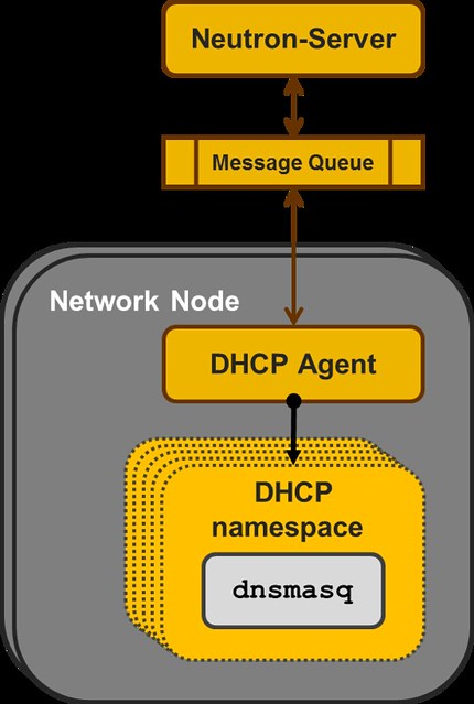
Just as a quick overview, the current reference implementation for DHCP in OpenStack Neutron is a centralized agents that manages multiple instances of the DNSMASQ Linux application, at least one per subnet configured with DHCP.

Each DNSMASQ instance runs in a dedicated Linux namespace, and you have one per a tenant's subnet (e.g. 5 tenants, each with 3 subnets = 15 DNSMASQ instances running in 15 different namespaces on the Network Node).


Neutron DHCP Agent 


The concept here is to use "black boxes" that each implement some specialized functionality as the the backbone of the IaaS.

And in this manner, the DHCP implementation is similar to how Neutron L3 Agent and the Virtual Router namespaces are implemented.

However, for the bigger scale deployments there are some issues here:

Management  - You need to configure, manage and maintain multiple instances of DNSMASQ.  HA is  achieved by running an additional DNSMASQ instance per subnet on a different  Node which adds another layer of complexity.  

Scalability - As a centralized solution that depends on the Nodes that run the DHCP Agents (aka Network Node), it has serious limitations in scale.  As the number of tenants/subnets grow, you add more and more running instances of DNSMASQ, all on the same Nodes. If you want to split the DNSMASQs to more Nodes, you end-up with significantly worse management complexity.   

Performance - Using both a dedicated Namespace and a dedicated DNSMASQ process instance per subnet is relatively resource heavy.  The resource overheads for each tenant subnet in the system should be much smaller. Extra network traffic, The DHCP broadcast messages are sent to all the Nodes hosting VMs on that Virtual L2 domain. 

Having said that, the reference implementation DHCP Agent is stable mature and used in production while the concept we discuss in the next paragraph is in a very early stage in the development cycle.


Dragonflow Distributed DHCP

When we set up to develop the DHCP application for the Dragonflow Local Controller, we realized we had to first populate all the DHCP control data to all the relevant local controllers.

In order to do that, we added the DHCP control data to our distributed database.  

More information about our database can be found in Gal Sagie's post:
Dragonflow Pluggable Distributed DB

Next, we added a specialized DHCP service pipeline to Dragonflow's OpenFlow pipeline.


  1. A classification flow to match DHCP traffic and forward it to the DHCP Table was added to the Service Table
  2. In the DHCP Table we match by the in_port of each VM that is connected to a subnet with a DHCP Server enabled
  3. Traffic from VMs on subnets that don't have a DHCP Server enabled are resubmitted to the L2 Lookup Table, so that custom tenant DHCP Servers can still be used
  4. For packets that were successfully matched in the DHCP Table we add the port_id to the metadata, so that we can do a fast lookup in the Controller database, and then we forward the packet to the Controller
  5. In the Controller, we forward the PACKET_IN with the DHCP message to the DHCP SDN Application.
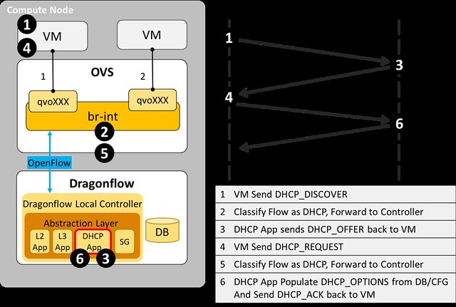
  6. In the DHCP Application, we handle DHCP_DISCOVER requests and generate a response with all the DHCP_OPTIONS that we send directly to the source port.
The diagram below illustrate the DHCP message flow from the VM to the local controller.
  
DHCP message flow


Benefits of Dragonflow Distributed DHCP

Simplicity - There is no additional running process(es).  The one local controller on each compute node does it all, for all subnets and all tenants
Scalability - Each local controller deals only with the local VMs
Stability - One process per compute node is easy to make sure is running at all times
Performance - DHCP traffic is handled directly at the compute node and never goes on the network

And there are surely many more benefits to this approach, feel free to post them as comments.


I want it! How do I get it?

The source code of this newly developed service in available here, and you could try it today (just follow the Dragonflow installation guide).

We are currently working on improving the stability of the L2, L3 and DHCP services of the Dragonflow local controller for OpenStack Liberty release.

The Dragonflow Community is growing and we would love to have more people joining to contribute to its success.

For any questions, feel free to contact us on IRC #openstack-dragonflow 

Tuesday, August 4, 2015

Centralized vs. Distributed SDN Control Path Paradigm

In a previous post I covered some misconceptions about SDN management and my view of the importance of the hybrid(proactive/reactive) model for scalability, and how we used this approach in the design of Dragonflow.

Today, i will discuss the two existing paradigms to SDN control path, and how it affects our road map in the Dragonflow project.

The first approach is the Centralized Controller.  Here, a controller (or a cluster of them) manages all the forwarding elements in the system, and retains a global view of the entire network. 

Most SDN controllers today run this way (ODL, ONOS, as well as Kilo version of Dragonflow).

The second approach is the Distributed Control Path.  Here, a local controller runs on each compute node and manages the forwarding element directly (and locally).  Thus, the control plane becomes distributed across the network.  

However, the virtual network topology needs to be synchronized across all the local controllers, and this is accomplished by using a distributed database.

Like everything else in life, there are advantages and disadvantages to each approach.  So, let's compare: 


Centralized Control Path


Pros


  • The controller has a global view of the network, and it can easily ensure that the network is in a consistent, optimal configuration
  • Simpler, agentless solution - Nothing needs to be installed on the compute nodes 
  • Any and all southbound APIs can be supported directly from the centralized controller (easier to integrate with legacy equipment)

Cons

  • Added latency in newly established flows, becomes a bottleneck in large scale deployments
  • Dependency on the controller cluster availability and scale
  • All advanced services are handled centrally, instead of locally, perpetuating a bottleneck as the scale grows
  • Large scale is usually controlled via BGP-based Confederations and multiple SDNC clusters which add more latency and complexity

Distributed Control Path


Pros

  • You can manage policies and introduce advanced services locally on each compute node, since you already have a local footprint
  • Significantly better scalability, now that you have the control plane completely distributed
  • Significantly better latency during reactive handling of PACKET_IN
  • Highly-available by design and no single-point-of-failure
  • Easier to integrate Smart NIC capabilities on local host level

Cons

  • Synchronization of the virtual network topology can be a challenge, as the amount of compute nodes increases
  • No global view
  • Extra compute is done on the local host
  • If you have heterogeneous forwarding elements (e.g. legacy switches), you need to have a centralized controller that connects them to the distributed control plane (which can complicate the management) 


What we chose and why


We decided earlier-on to go with a hybrid reactive/proactive model (against the widely-accepted proactive-only approach), as we saw that its advantages were overwhelming.  

The winning point of the reactive mode, as we see it, is that it improves the performance of the datapath, taking the performance toll instead on the control path of newly-established flows.  The main reason for that being a dramatic reduction of the number of flows that are installed into the forwarding element.

When combined with a pipeline that is deployed proactively, we could maximize the benefits of the reactive approach, while minimizing its cost.

However, like all solutions, at a certain scale it will break.


In very large deployments (e.g. a full datacenter), a central controller cluster becomes overwhelmed with the increase in volume of new connections.

A centralized controller made sense, while we were only handling new L3 connection path establishment (Dragonflow in Kilo).

However, when we came to add reactive L2 and other advanced services (like DHCP, LB, etc.), we realized that scaling the centralized controller cluster was becoming a huge challenge. 

A different approach must now be taken, and we believe this approach is to place a local controller on each compute node.  

Now that the control path bottleneck was mitigated, the problem moves to the logical data distribution between all the local controllers.

To mitigate that, we believe we can reuse the reactive approach, by letting the local controllers synchronize only the data they actually need (in lazy mode) use key/value distributed db engines that provide low latency. 

Sure, this will probably take some performance toll on the establishment of new flows, but we believe it will dramatically reduce the amount of data synchronization required, and therefore will take us to the next scalability level.


What we are doing in Dragonflow


We are currently working on introducing reactive L2 and L3 model into the local Draongflow controller.  

We are creating a pluggable distributed database mechanism to serve the logical data across the datacenter, which will enable the user to chose the best database to meet their specific needs and scale.

As always, we would love to have more people join the Dragonflow community and contribute to its success.

For additional information about the pluggable database layer, you can check out Gal Sagie's new blog post.

Sunday, July 26, 2015

Voting for my talks in OpenStack Tokyo 2015

I've submitted several talks to OpenStack Tokyo 2015.
If you find anything here interesting, please vote for it.

(note: you need to have an account in openstack.org to do it)


My submitted talks need your votes:

Dragonflow – L3 Deep dive and hands on lab


OpenVSwitch Scale Performance secrets revealed – and open source solutions


Network high availability by design


Scaling Neutron - Distributing Advanced Services using SDN


Say Hello to 100G OpenStack Networking by Offloading SDN flows using DragonFlow and intelligent NICs (joint talk with Mellanox)


Multi Site Openstack - Deep dive  (joint talk with Midokura)


Thanks for your vote, and see you there.


Tuesday, May 5, 2015

DragonFlow SDN based Distributed Virtual Router for OpenStack Neutron

In my previous posts I presented a PoC implementation of an embedded L3 controller in Neutron that solves the network node bottleneck the SDN way, and overcomes some of the DVR limitations.
In this post I am going to cover the first release of DragonFlow - an SDN based Distributed Virtual Router L3 Service Plugin (aligned with OpenStack Kilo), now an official sub-project of Neutron.
The main purpose of DragonFlow is to simplify the management of the virtual router while improving performance, scale and eliminating single point of failure together with the network node bottleneck.
The DrangonFlow solution is based on separation of the routing control plane from the data plane. This is accomplished by implementing the routing logic in distributed forwarding rules on the virtual switches (called "flows" in OpenFlow terminology). To put this simply, the virtual router is implemented using OpenFlow flows only.
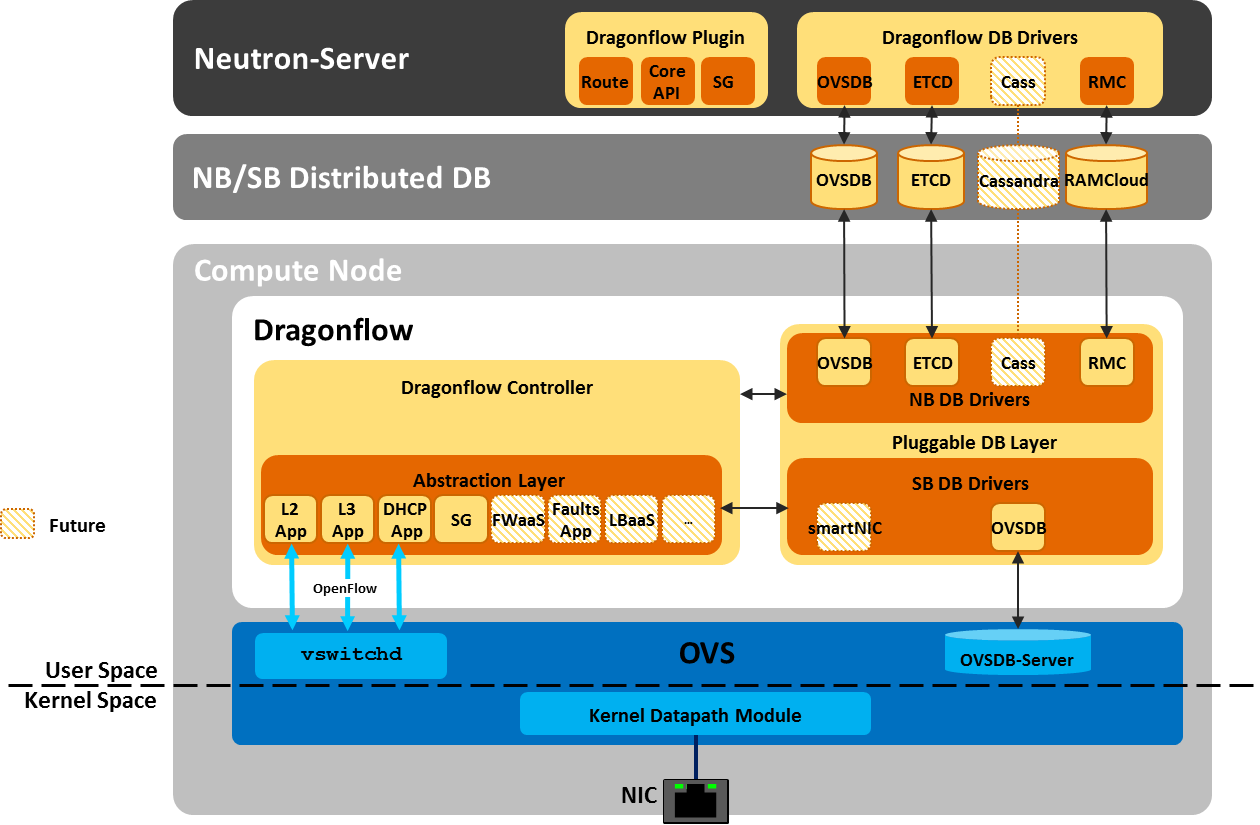
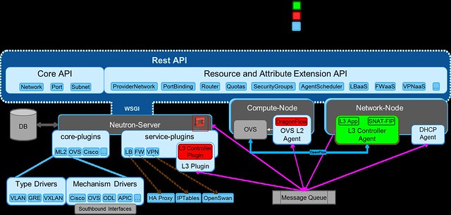
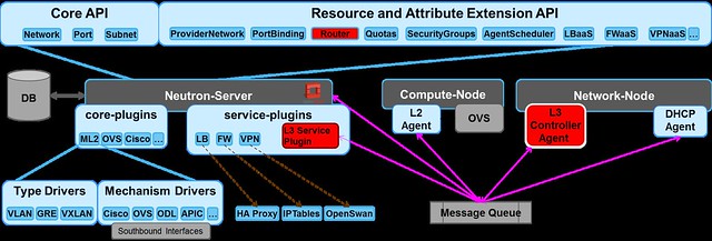
DragonFlow eliminates the use of software stack to act as a virtual router (the Linux network namespaces in the DVR and the legacy L3 architecture), it use purely OVS flow to act as a virtual router. A diagram showing DragonFlow components and overall architecture can be seen here:
DragonFlow High-level Architecture


DragonFlow Features for the Kilo Release:

  • East-West traffic is fully distributed using direct flows, reactively installed upon VM-to-VM first connection.
  • Support for all ML2 type drivers GRE/VXLAN/VLAN
  • Support for centralized shared public network (SNAT) based on the legacy L3 implementation
  • Support for centralized floating IP (DNAT) based on the legacy L3 implementation
  • Support for HA, in case the connection to the Controller is lost, fall back to the legacy L3 implementation until recovery. Reused all the legacy L3 HA. (Controller HA will be supported in the next release).


Key Advantages:

  • Performance improvements for inter-subnet network communication by removing the number of kernel layers (namespaces and their TCP stack overhead)
  • Scalability improvements for inter-subnet network communication by offloading L3 East-West routing from the Network Node to all Compute Nodes
  • Reliability improvements for inter-subnet network communication
  • Simplified virtual routing management, mange only active flows and not all possible 
  • Non Intrusive solution, does not rely on ML2 modification

How it works

  1. On bootstrap the L3 service plugin sends an RPC message to the L2 service plugin, setting the L3  Controller Agent as the controller of the integration bridge.
  2. The Controller queries the OVS  for its port configuration via Openflow, matches the actual ports configured on the OVS to the Neutron tenant networks data model. 
  3. Then, it installs the bootstrap flow pipeline that offloads all L2 traffic and local subnet L3 traffic into the NORMAL pipeline, while sending every unmatched VM-to-VM inter-sunbet traffic to the controller.
DragonFlow L3 Service Bootstrap

The following diagram shows the multi-table OpenFlow pipeline installed onto the OVS integration bridge (br-int) in order to represent the virtual router using flows:

bootstrap flows pipeline

The base table pipe-line is installed proactively on bootstrap while the East-West rules on the L3 Forwarding table are installed reactively on each first VM-to-VM communication.

If you would like to try it yourself, install guide is available here.
To join the development effort: 
My next post will cover the L3 reactive OpenFlow application, and how we install the East-West reactive flows. 

Thursday, January 22, 2015

Neutron DVR The SDN Way

In my previous posts I covered the existing Openstack virtual L3 implementations, from the base centralized implementation to the state of the art solution, DVR, that distributes the load among the computes nodes.

I also summarized the limitations of DVR and hopefully convinced you of the motivation for yet another L3 implementation in Neutron.

Just to quickly recap, the approach for DVR’s design was to take the existing centralized router implementation based on Linux network namespaces and clone it on all compute nodes. This is an evolutionary approach and a reasonable step to take in distributing L3 from which we've learned a lot. However, this solution is far form optimal.

In this post I’m going to present a PoC implementation of an embedded L3 controller in Neutron that solves the same problem (the network node bottleneck) the SDN way, and overcomes some of the DVR limitations.

I chose to start with just the East-West traffic, and leave the North-South for the next step.


I will share some of my ideas for North-South implementation in upcoming posts, as well as links to the Stackforge project.


If you're interested in joining the effort or take the code for a test drive, feel free to email me or leave a comment below.


SDN Controllers are generally perceived as huge pieces of complex code with hundreds of thousands of lines of code that try to handle everything.  It's natural that people would not deem such software to be capable of running "in line".  However, this is not necessarily so.  As I will demonstrate, the basic SDN Controller code can be separated and deployed in a lean and lightweight manner.

It occurred to me that by combining the well-defined abstraction layers already in Neutron (namely the split into br-tun, br-int and br-ext) and a lightweight SDN controller that can be embedded directly into Neutron, it will be possible to solve the network node bottleneck and the L3 high-availability problems in the virtual overlay network in a simple way.

Solution overview 

The proposed method is based on the separation of the routing control plane from the data plane. This is accomplished by implementing the routing logic in distributed forwarding rules on the virtual switches. In OpenFlow these rules are called flows. To put this simply, the virtual router is implemented in using OpenFlow flows. 
The functionality of the virtual routes that we should address in our solution is:


  • L3 routing
  • ARP response for the router ports
  • OAM, like ICMP (ping) and others


L3 Controller embedded in Neutron POC


We decided to create our controller PoC with Openstack design tenets in mind. Specifically the following:

  1. Scalability     - Support thousands of compute nodes
  2. Elasticity       - Keep controllers stateless to allow for dynamic growth 
  3. Performance  - Improve upon DVR
  4. Reliability      - Highly available
  5. Non intrusive - Rely on the existing abstraction and plug-able module

What we intend to prove is:
  • We indeed simplify the DVR flows
  • We reduce resource overhead (e.g. bridges, ports, namespaces)
  • We remove existing bottlenecks (compared to L3Agent and DVR)
  • We improve performance
We've started benchmarking the different models and I'll post results as soon as we have them ready.


Reactive vs. Proactive Mode

SDN defines two modes for managing a switch: reactive and proactive.
In our work, We decided to combine these two modes so that we could benefit from the advantages of both modes (although if you believe the FUD about the reactive mode performance, it is quite possible to enhance it to be purely proactive). To learn more about this mixed mode see my previous blog


The Proactive part

In the solution we install a flow pipeline in the OVS br-int in order to offload the handling of L2 and intra-subnet L3 traffic by forwarding these to the NORMAL path (utilizing the hybrid OpenFlow switch). This means that we reuse the built in mechanisms in Neutron for all L2 traffic (i.e. ML2 remains untouched and fully functional) and for L3 traffic that does not need routing (between IPs in the same tenant + subnet).
In addition we use the OVS OpenFlow extensions in order to install an ARP responder for every virtual router port. This is done to offload ARP responses to the compute nodes instead of replying from the controller.


The Reactive part

Out of the remaining traffic (i.e. inter-subnet L3 traffic) the only traffic that is handled in a reactive mode is the first packet of inter-subnet communications between VMs or traffic addressed directly to the routers' ports.


The Pipeline

Perhaps the most important part of the solution is the OpenFlow pipeline which we install into the integration bridge upon bootstrap.
This is the flow that controls all traffic in the OVS integration bridge (br-int).
The pipeline works in the following manner:


  1. Classify the traffic
  2. Forward to the appropriate element:
    1. If it is ARP, forward to the ARP Responder table
    2. If routing is required (L3), forward to the L3 Forwarding table (which implements a virtual router)
    3. Otherwise, offload to NORMAL path
At the end of this post is a detailed explanation of the pipeline and implementation brief in case you're interested in the gory details.


In my following posts I will cover in detail the code modifications that were required to support the L3 controller as well as publish a performance study comparing the L3 Agent, DVR and the L3 controller for inter subnet traffic.

If you want to try it out, the code plus installation guide  are available here.


Again, if you'd like to join the effort, feel free to get in touch.


detailed explanation of the pipeline

The following diagram shows the multi-table OpenFlow pipeline installed into the OVS integration bridge (br-int) in order to represent the virtual router using flows only:
L3 Flows Pipeline


The following table describes the purpose of each of the pipeline tables:


ID
Table Name
Purpose
0
Metadata &
Dispatch
  • Tag traffic with the appropriate metadata by input port, the value is the segmentation ID
  • Input traffic from the tunnel bridge is offloaded to the NORMAL path
  • All other traffic is sent to the "Classifier" table for classification
40
Classifier
  • All ARP traffic is sent to the ARP responder table
  • All broadcast and multicast traffic is offloaded to the Normal path
  • All L3 traffic is sent to the L3 forwarding table
51
ARP Responder
  • This table handles ARP responses for the virtual router interfaces.
  • The vlan tag is removed from all other traffic and offloaded to the NORMAL path
52
L3 Forwarding
  • This table is used by the Controller to install flows to handle VM to VM inter subnet traffic (detailed explanation below)
  • Traffic destined for a virtual router is sent to the controller (e.g. ping, packet_in, etc)
  • All local subnet traffic is offloaded to the NORMAL path
  • All other traffic is sent to the public network table
53
Public Network
  •  will be described in following blogs


PoC Implementation brief

For the first release, we used the Open vSwitch (OVS), with OpenFlow v1.3 as the southbound protocol, using the RYU project implementation of the protocol stack as a base library.
The PoC support Route API for IPV4 East -West traffic.  
In the current PoC 

implementation, the L3 controller is embedded into  the  L3 service plugin.