In this 3-post series I cover how DVR works in (just about enough) detail.
I assume you know how virtual routing is managed in Neutron.
Up until Juno, all L3 traffic was sent through the network node, including even traffic between VMs residing on the same physical host.
This, of course, created a bottleneck, as well as a single point of failure (SPOF).
In Juno, DVR was introduced to overcome these problems.
As I described in my previous post, L3 networking in Neutron is divided into 3 main services:
The main idea of DVR is to distribute the L3 Agent functionality to all the compute nodes, distributing the load and eliminating the SPOF.
DVR successfully distributes the first two services.
However, SNAT distribution is not covered by DVR, and remains to be handled by hitting the Network Node in a centralized manner.
The main challenges for SNAT distribution were maintaining the FWaaS
statefulness and conserving IP addresses from the public network address pool (since supporting these will require each compute node to have a public IP address).
DVR implements a virtual router element on every compute node using the Linux network namespace (similarly to L3 Agent virtual router).
This is achieved by cloning the current centralized L3 implementation onto every compute node.
For each service, this is handled in a different manner.
All the ARP entries for networks attached to each DVR are proactively populated by the L3 DVR Agent on all the cloned virtual router namespaces, i.e. on all the compute nodes that participate.
In order to avoid having traffic from different physical hosts using the same MAC (which, as we said, we are reusing), each of the cloned DVRs is assigned a system-wide unique MAC address.
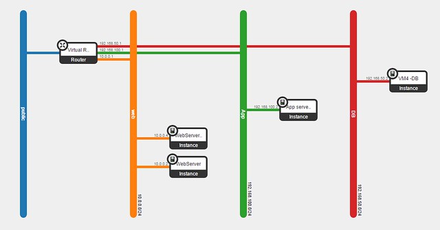
I will reuse the example from my previous post: the popular cloud deployment
3-tier web application design pattern (www-app-db).
In Horizon, we set up 3 subnets (in addition to the public) with one virtual router to bind them all.
On each compute node, the DVR namespace is pre-configured with the following:
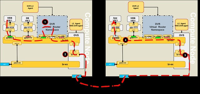
As we can see, VM1 on Web subnet communicates with VM3 on App subnet:
 Note that the reverse flow goes in a different route (see the blue line).
I assume you know how virtual routing is managed in Neutron.
Up until Juno, all L3 traffic was sent through the network node, including even traffic between VMs residing on the same physical host.
This, of course, created a bottleneck, as well as a single point of failure (SPOF).
In Juno, DVR was introduced to overcome these problems.
As I described in my previous post, L3 networking in Neutron is divided into 3 main services:
- East-West communication: IP traffic between VMs in the data center
- Floating IP (aka DNAT): The ability to provide a public IP to a VM, making it directly accessible from public networks (i.e. internet)
- Shared IP (aka SNAT): The ability to provide public network access to VMs in the data center using a shared (public) IP address
The main idea of DVR is to distribute the L3 Agent functionality to all the compute nodes, distributing the load and eliminating the SPOF.
DVR successfully distributes the first two services.
However, SNAT distribution is not covered by DVR, and remains to be handled by hitting the Network Node in a centralized manner.
The main challenges for SNAT distribution were maintaining the FWaaS
statefulness and conserving IP addresses from the public network address pool (since supporting these will require each compute node to have a public IP address).
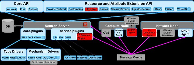 |
| Neutron components with DVR entities are shown in red |
This is achieved by cloning the current centralized L3 implementation onto every compute node.
For each service, this is handled in a different manner.
Inter subnet routing East-West
All the cross subnet traffic (between VMs of the same tenant) in DVR is now handled locally on the compute node using the router namespace.
A Linux namespace is created for every virtual router, on each compute node that hosts VMs that are connected to that router.
In order to configure these local DVR namespaces, the DVR L3 Agent (which used to be deployed only to the network node) is deployed onto all compute nodes as you can see in the diagram below.

Now, extra OVS flows were required to enable the DVR functionality. To do that, enhancements were applied to L2 OVS Agent. These enhancements are described below.
In order to simplify management, the same IP and MAC addresses are reused on all the compute node DVRs, i.e. a single {IP, MAC} per virtual router port).
Owing to this, ARP traffic for the virtual router ports is kept local to the compute node.
A Linux namespace is created for every virtual router, on each compute node that hosts VMs that are connected to that router.
In order to configure these local DVR namespaces, the DVR L3 Agent (which used to be deployed only to the network node) is deployed onto all compute nodes as you can see in the diagram below.
Now, extra OVS flows were required to enable the DVR functionality. To do that, enhancements were applied to L2 OVS Agent. These enhancements are described below.
In order to simplify management, the same IP and MAC addresses are reused on all the compute node DVRs, i.e. a single {IP, MAC} per virtual router port).
Owing to this, ARP traffic for the virtual router ports is kept local to the compute node.
All the ARP entries for networks attached to each DVR are proactively populated by the L3 DVR Agent on all the cloned virtual router namespaces, i.e. on all the compute nodes that participate.
In order to avoid having traffic from different physical hosts using the same MAC (which, as we said, we are reusing), each of the cloned DVRs is assigned a system-wide unique MAC address.
I will reuse the example from my previous post: the popular cloud deployment
3-tier web application design pattern (www-app-db).
In Horizon, we set up 3 subnets (in addition to the public) with one virtual router to bind them all.
On each compute node, the DVR namespace is pre-configured with the following:
- Port MAC and IP addresses
- Routing tables (default route per subnet and static routes)
- ARP table entries for all the VMs in the connected networks
- Isolate DVR broadcast domain to be local to the integration bridge
- Translate the globally assigned MAC of the DVR into the local MAC address and vice versa
- Redirect traffic correctly per VM (new flows are installed for every new VM started on the compute node)
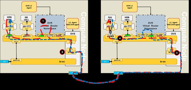
 |
| Realization of our topology on 2 Compute nodes |
- The packet reaches the subnet GW port on the local compute node
- It is routed using the DVR namespace routing table into the destination subnet
- Linux namespace then performs the followings actions on the packet:
- Use the pre-populated ARP table to set the destination MAC address
- Set the source MAC to the local DVR GW port of the destination subnet
- On the tunnel bridge the source MAC is replaced with the global DVR MAC address
- The packet reaches the compute node that hosts the destination VM:
- The segmentation ID is replaced with the local vlan
- The packet is matched by the global source MAC address and forwarded to the integration bridge
- The packet source MAC is replaced with the appropriate local DVR GW MAC and forwarded directly to the destination VM port
In the reverse flow from VM3 to VM1, packets are routed through the local DVR instance of the compute node that hosts VM3.

Due to this behavior, we cannot create stateful East-West rules, hence FWaaS for East-West traffic is not supported by DVR Juno.