In this post, the last of a 3-post series about Openstack Juno DVR, I go into the North-South SNAT scenario in details.
Up until Juno, all L3 traffic was sent through the network node. In Juno, DVR was introduced to distribute the load from the network node onto the compute nodes.
The L3 networking in Neutron is divided into 3 main services:
- East-West communication: IP traffic between VMs in the data center
- Floating IP (aka DNAT): The ability to provide a public IP to a VM, making it directly accessible from public networks (i.e. internet)
- Shared IP (aka SNAT): The ability to provide public network access to VMs in the data center using a shared (public) IP address
In my previous posts, I covered how DVR distributes the the East-West L3 traffic and the DNAT North-South.
In this post I finish covering the North-South traffic with the Shared IP (SNAT).
SNAT Shared Gateway North-South
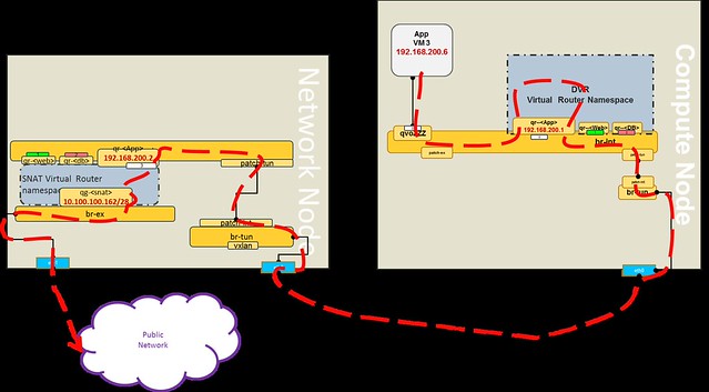
The SNAT North-South shared public gateway functionality was not distributed by DVR. It remains centralized on the Network Node, as you can see in the diagram below.
 In order to configure the SNAT namespaces on the Network node, the SNAT-DVR L3 agent is deployed.
An additional private address is assigned in the SNAT namespace for each of the DVR connected subnets, thus providing the centralized SNAT functionality.
Lets follow a communication flow from VM3 in the App network to the public network.
In my next post I will summarize the DVR solution in Openstack Juno.
An additional private address is assigned in the SNAT namespace for each of the DVR connected subnets, thus providing the centralized SNAT functionality.
Lets follow a communication flow from VM3 in the App network to the public network.
- The packet is forwarded to the DVR namespace via the local DVR default gateway port
- If the packet destination is not private, then it is routed to the appropriate default public gateway port (based on the source subnet) on the SNAT namespace
- An OVS flow converts the local VLAN into the App network segmentation ID
- The packet is forwarded into the SNAT namespace and NAT-ed using the SNAT public address
Let's look at a concrete example:
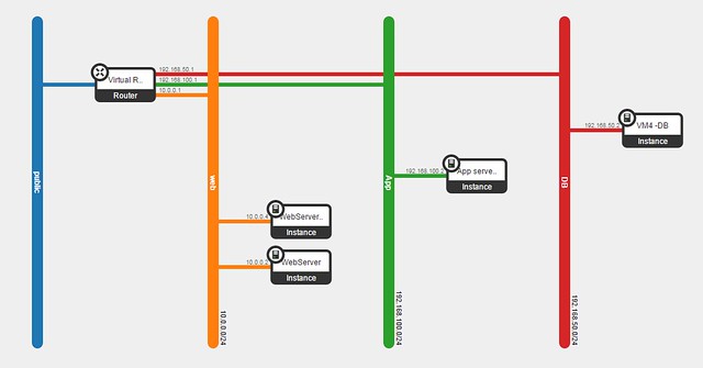
[Public Network range]=10.100.100.160/28
[App Network]=192.168.200.0/24
[Shared Public IP (SNAT)]=10.100.100.162
[VM3 private IP]=192.168.200.6

In my next post I will summarize the DVR solution in Openstack Juno.
Questions and comments are welcome.
The configuration files I used to set-up the Openstack Neutron into DVR mode can be found here.
The configuration files I used to set-up the Openstack Neutron into DVR mode can be found here.