Showing posts with label distributed virtual router. Show all posts

Saturday, September 26, 2015

Dragonflow Distributed DHCP for OpenStack Neutron done the SDN way

In the previous post we explained why we chose the distributed control path approach (local controller) for Dragonflow.

Lately, we have been getting a lot of questions about DHCP service, and how it could be made simpler with an SDN architecture.

This post will therefore focus on the Dragonflow DHCP application (recently released).  

We believe it is a good example for Distributed SDN architecture, and to how policy management and new advanced network services that run directly at the Compute Node simplify and improve the OpenStack cloud stability and manageability.

Just as a quick overview, the current reference implementation for DHCP in OpenStack Neutron is a centralized agents that manages multiple instances of the DNSMASQ Linux application, at least one per subnet configured with DHCP.

Each DNSMASQ instance runs in a dedicated Linux namespace, and you have one per a tenant's subnet (e.g. 5 tenants, each with 3 subnets = 15 DNSMASQ instances running in 15 different namespaces on the Network Node).
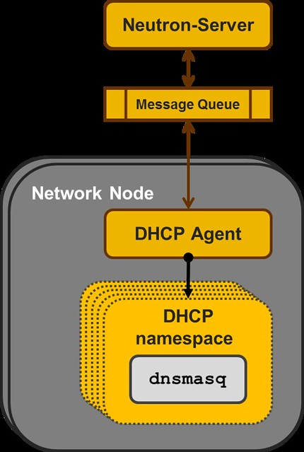

Neutron DHCP Agent 


The concept here is to use "black boxes" that each implement some specialized functionality as the the backbone of the IaaS.

And in this manner, the DHCP implementation is similar to how Neutron L3 Agent and the Virtual Router namespaces are implemented.

However, for the bigger scale deployments there are some issues here:

Management  - You need to configure, manage and maintain multiple instances of DNSMASQ.  HA is  achieved by running an additional DNSMASQ instance per subnet on a different  Node which adds another layer of complexity.  

Scalability - As a centralized solution that depends on the Nodes that run the DHCP Agents (aka Network Node), it has serious limitations in scale.  As the number of tenants/subnets grow, you add more and more running instances of DNSMASQ, all on the same Nodes. If you want to split the DNSMASQs to more Nodes, you end-up with significantly worse management complexity.   

Performance - Using both a dedicated Namespace and a dedicated DNSMASQ process instance per subnet is relatively resource heavy.  The resource overheads for each tenant subnet in the system should be much smaller. Extra network traffic, The DHCP broadcast messages are sent to all the Nodes hosting VMs on that Virtual L2 domain. 

Having said that, the reference implementation DHCP Agent is stable mature and used in production while the concept we discuss in the next paragraph is in a very early stage in the development cycle.


Dragonflow Distributed DHCP

When we set up to develop the DHCP application for the Dragonflow Local Controller, we realized we had to first populate all the DHCP control data to all the relevant local controllers.

In order to do that, we added the DHCP control data to our distributed database.  

More information about our database can be found in Gal Sagie's post:
Dragonflow Pluggable Distributed DB. 

Next, we added a specialized DHCP service pipeline to Dragonflow's OpenFlow pipeline.


  1. A classification flow to match DHCP traffic and forward it to the DHCP Table was added to the Service Table
  2. In the DHCP Table we match by the in_port of each VM that is connected to a subnet with a DHCP Server enabled
  3. Traffic from VMs on subnets that don't have a DHCP Server enabled are resubmitted to the L2 Lookup Table, so that custom tenant DHCP Servers can still be used
  4. For packets that were successfully matched in the DHCP Table we add the port_id to the metadata, so that we can do a fast lookup in the Controller database, and then we forward the packet to the Controller
  5. In the Controller, we forward the PACKET_IN with the DHCP message to the DHCP SDN Application.
  6. In the DHCP Application, we handle DHCP_DISCOVER requests and generate a response with all the DHCP_OPTIONS that we send directly to the source port.
The diagram below illustrate the DHCP message flow from the VM to the local controller.
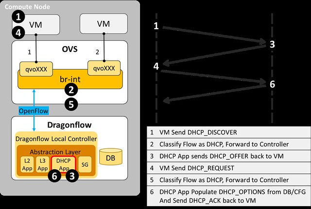
  
DHCP message flow


Benefits of Dragonflow Distributed DHCP

Simplicity - There is no additional running process(es).  The one local controller on each compute node does it all, for all subnets and all tenants
Scalability - Each local controller deals only with the local VMs
Stability - One process per compute node is easy to make sure is running at all times
Performance - DHCP traffic is handled directly at the compute node and never goes on the network

And there are surely many more benefits to this approach, feel free to post them as comments.


I want it! How do I get it?

The source code of this newly developed service in available here, and you could try it today (just follow the Dragonflow installation guide).

We are currently working on improving the stability of the L2, L3 and DHCP services of the Dragonflow local controller for OpenStack Liberty release.

The Dragonflow Community is growing and we would love to have more people joining to contribute to its success.

For any questions, feel free to contact us on IRC #openstack-dragonflow 

Tuesday, May 5, 2015

DragonFlow SDN based Distributed Virtual Router for OpenStack Neutron

In my previous posts I presented a PoC implementation of an embedded L3 controller in Neutron that solves the network node bottleneck the SDN way, and overcomes some of the DVR limitations.
In this post I am going to cover the first release of DragonFlow - an SDN based Distributed Virtual Router L3 Service Plugin (aligned with OpenStack Kilo), now an official sub-project of Neutron.
The main purpose of DragonFlow is to simplify the management of the virtual router while improving performance, scale and eliminating single point of failure together with the network node bottleneck.
The DrangonFlow solution is based on separation of the routing control plane from the data plane. This is accomplished by implementing the routing logic in distributed forwarding rules on the virtual switches (called "flows" in OpenFlow terminology). To put this simply, the virtual router is implemented using OpenFlow flows only.
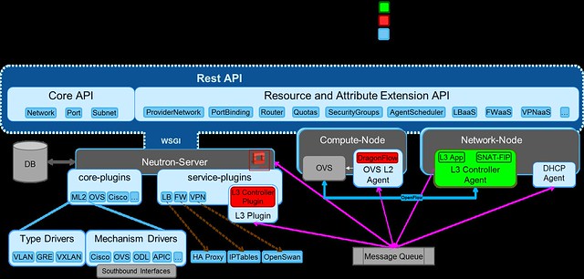
DragonFlow eliminates the use of software stack to act as a virtual router (the Linux network namespaces in the DVR and the legacy L3 architecture), it use purely OVS flow to act as a virtual router. A diagram showing DragonFlow components and overall architecture can be seen here:
DragonFlow High-level Architecture


DragonFlow Features for the Kilo Release:

  • East-West traffic is fully distributed using direct flows, reactively installed upon VM-to-VM first connection.
  • Support for all ML2 type drivers GRE/VXLAN/VLAN
  • Support for centralized shared public network (SNAT) based on the legacy L3 implementation
  • Support for centralized floating IP (DNAT) based on the legacy L3 implementation
  • Support for HA, in case the connection to the Controller is lost, fall back to the legacy L3 implementation until recovery. Reused all the legacy L3 HA. (Controller HA will be supported in the next release).


Key Advantages:

  • Performance improvements for inter-subnet network communication by removing the number of kernel layers (namespaces and their TCP stack overhead)
  • Scalability improvements for inter-subnet network communication by offloading L3 East-West routing from the Network Node to all Compute Nodes
  • Reliability improvements for inter-subnet network communication
  • Simplified virtual routing management, mange only active flows and not all possible 
  • Non Intrusive solution, does not rely on ML2 modification

How it works

  1. On bootstrap the L3 service plugin sends an RPC message to the L2 service plugin, setting the L3  Controller Agent as the controller of the integration bridge.
  2. The Controller queries the OVS  for its port configuration via Openflow, matches the actual ports configured on the OVS to the Neutron tenant networks data model. 
  3. Then, it installs the bootstrap flow pipeline that offloads all L2 traffic and local subnet L3 traffic into the NORMAL pipeline, while sending every unmatched VM-to-VM inter-sunbet traffic to the controller.
DragonFlow L3 Service Bootstrap

The following diagram shows the multi-table OpenFlow pipeline installed onto the OVS integration bridge (br-int) in order to represent the virtual router using flows:

bootstrap flows pipeline

The base table pipe-line is installed proactively on bootstrap while the East-West rules on the L3 Forwarding table are installed reactively on each first VM-to-VM communication.

If you would like to try it yourself, install guide is available here.
To join the development effort: 
My next post will cover the L3 reactive OpenFlow application, and how we install the East-West reactive flows. 

Thursday, January 8, 2015

Openstack Neutron DVR - Summary

Following my 3-post series about Openstack Juno DVR in detail, this post is a summary of DVR, in my point of view.

In the next post I’m going to present a POC implementation of an embedded L3 controller in Neutron that solves the problem differently. In this post I’d like to explain the motivation for yet another L3 implementation in Neutron.

I believe the L3 Agent drawbacks are pretty clear (centralized bottleneck, limited HA, etc), so in this post I’m going to cover the key benefits and drawbacks of DVR as I see them. So without further ado, let’s start.

Pros


First of all, from a functional point of view, DVR successfully distributed the East-West traffic and the DNAT floating IP, which provided significant offload from the Network node contention. This achieved two key benefits, first is that the failure domains are much smaller (Network node failure only affects SNAT) and the second is scalability due to the distribution of the load on all the compute nodes. 


Cons

The approach for DVR’s design was to take the existing centralized router implementation based on Linux network namespaces and clone it on all compute nodes. This is an evolutionary approach and an obvious step to take in distributing L3 from which we’ve learned a lot from. However, it adds load and complexity in three major areas: Management, Performance and Code.

To explain the technical details I will briefly cover two Linux networking constructs used in the solution for East-West communications:

1. Linux network namespaces (which internally load a complete TCP/IP stack with ARP tables and routing tables)
2. OVS flows

OVS flows were needed in order to block the local ARP, redirect return traffic directly to the VMs and to replace the router ports MAC (which cannot be accomplished reasonably using namespaces alone). On the flip side, OVS flows can easily accomplish everything that DVR uses the namespaces for (in East-West communications) and perhaps more importantly it does so in a more efficient way (avoids the overhead of the extra TCP/IP stack etc). To hint at our solution, flows also allow us to further improve the solution by selectively using a reactive approach where relevant.


Extra Flows Install for DVR
So overall it seems that using the Linux network namespace as a black box to emulate a router is an overkill. This approach makes sense in the centralized solution (L3 Agent) where for each tenant’s virtual router we use a single namespace in the DC, however, in the distributed approach where the number of namespaces in the DC is multiplied by the number of compute nodes this needs to be reevaluated.
If you’re not convinced yet, here is a summary of the implications of using this approach:

Resource consumption and Performance

1. DVR adds an additional namespace as well as virtual ports per router on all compute nodes that host routed VMs. This means additional TCP/IP stacks that each and every cross subnet packet traverses. This adds latency and host CPU consumption.

2. ARP tables on all namespaces in the Compute nodes are proactively pre-populated with all the possible entries. Whenever a VM is started, all compute nodes which have running VMs from the same tenant will be updated to keep these tables up to date (which potentially adds latency to VM start time)

3. Flows and routing rules are proactively installed on all compute nodes.

Management complexity

1. Multiple configuration points that need to be synchronized: namespaces, routing tables, flow tables, ARP tables and IPTables.

2. Namespaces on all compute nodes need to be kept in sync all the time with the tenant’s VM ARP tables and routing information and need to be tracked to handle failures etc.

3. The current DVR implementation does not support a reactive mode (i.e. creating a flow just-in-time), thus all possible flows are created on all hosts, even If they’re never used.

Code Complexity

1. The DVR required cross-component changes due to its multi configuration points: The Neutron server Data Model, ML2 Plugin, L3 Plugin , OVS L2 Agent and the L3 Agent.

2. Using all Linux networking constructs in a single solution (namespaces, flows, linux bridges, etc) requiring code that can manage all of it.

3. The solution is tightly coupled with the overlay manager (ML2) which means that the addition of every new type driver (today only vxlan) requires code additions on all levels (as can be seen by the vlan patches)

In my next post I will present an alternative solution, we evaluated and developed (code available) for distributing the virtual router that attempts to overcome these limitations, using SDN technologies.

Comments, questions and corrections are welcome.

Thursday, January 1, 2015

3 Openstack Neutron Distributed Virtual Router (DVR) - Part 3 of 3

In this post, the last of a 3-post series about Openstack Juno DVR, I go into the North-South SNAT scenario in details.

Up until Juno, all L3 traffic was sent through the network node.  In Juno, DVR was introduced to distribute the load from the network node onto the compute nodes.

The L3 networking in Neutron is divided into 3 main services:
  1. East-West communication: IP traffic between VMs in the data center
  2. Floating IP (aka DNAT): The ability to provide a public IP to a VM, making it directly accessible from public networks (i.e. internet)
  3. Shared IP (aka SNAT): The ability to provide public network access to VMs in the data center using a shared (public) IP address
In my previous posts, I covered how DVR distributes the the East-West L3 traffic and the DNAT North-South.
In this post I finish covering the North-South traffic with the Shared IP (SNAT).

SNAT Shared Gateway  North-South 

The SNAT North-South shared public gateway functionality was not distributed by DVR.  It remains centralized on the Network Node, as you can see in the diagram below.


In order to configure the SNAT namespaces on the Network node, the SNAT-DVR L3 agent is deployed.

An additional private address is assigned in the SNAT namespace for each of the DVR connected subnets, thus providing the centralized SNAT functionality.

Lets follow a communication flow from VM3 in the App network to the public network. 
  1. The packet is forwarded to the DVR namespace via the local DVR default gateway port
  2. If the packet destination is not private, then it is routed to the appropriate default public gateway port (based on the source subnet) on the SNAT namespace 
  3. An OVS flow converts the local VLAN into the App network segmentation ID
  4. The packet is forwarded into the SNAT namespace and NAT-ed using the SNAT public address
Let's look at a concrete example:
[Public Network range]=10.100.100.160/28
[App Network]=192.168.200.0/24
[Shared Public IP (SNAT)]=10.100.100.162
[VM3 private IP]=192.168.200.6

In my next post I will summarize the DVR solution in Openstack Juno.

Questions and comments are welcome.

The configuration files I used to set-up the Openstack  Neutron into DVR mode can be found here.