In this multi-part blog series I intend to dive into the L3 Services in Neutron Openstack.
Neutron defines an API extension that allows Administrators and tenants to create virtual routers. The purpose of those is to connect several virtual L2 network subnets (which are defined using some other Neutron APIs).
Another API defined by Neutron and implemented in the L3 service is the Floating IP extension that provides public connectivity, whether directly to a VM (aka DNAT) or via shared gateway (aka SNAT).
The L3 Services in Neutron also handle the optional Extra Route extension API.
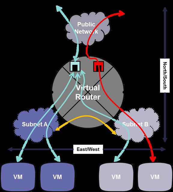 |
| Neutron Virtual Router |
In the above diagram we can see the following:
- Yellow: Inter subnet routing (East/West)
- Cyan: SNAT (port mapping and masquerading the IP address)
- Red: DNAT (floating IPs, public N/S connectivity directly to VM)
- Static routes (Extra Routes), defined inside the virtual router
Now, let's look at how everything gets wired when the system loads.
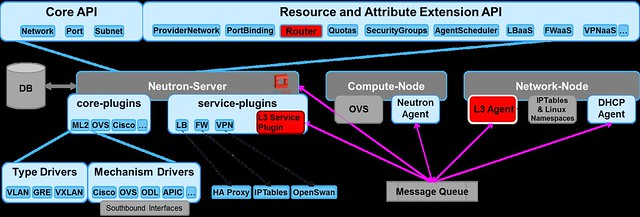
1. The L3 Service Plugin loads inside the Neutron server (which usually runs on the Controller Node). It handles the layer 3 RESTful APIs and the data access layer.
 |
| L3 Services API |
2. The L3 Agent usually runs on the Network Node. When started, it registers itself on the Neutron L3 Service Plugin Router Scheduler, via the Message Queue. It implements the virtual router functionality defined by the Neutron API.
4. Openstack Neutron reference implementation of the L3 Agent uses the Linux network namespaces and IPTables rules to implement the virtual routers.
5. The Linux network namespaces provide an isolated network stack with local routing table and IPTables rules. It enables reuse of IP addresses with scope limited to the namespace.
6. The L3 Agent creates a network namespace for each virtual router in the tenant network. Then, it creates all the virtual router ports inside the namespace.
7. Each virtual router port in the namespace is tagged in the integration bridge (aka br-int) with the local segmentation ID of the subnet.
8. Each virtual router namespace includes a gateway port to the external network (aka br-ex).
9. DNAT (Floating IP) and SNAT are implemented using IPTables rules that are applied on the gateway port.
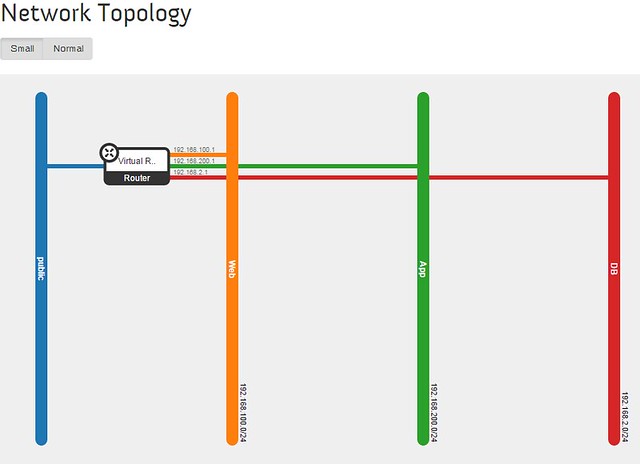
Let's take the popular cloud deployment 3-tier web application design pattern (www-app-db) as an example .
In Horizon, we set up 3 subnets (in addition to the external) with one virtual router to bind them all.
- The virtual router is realized by the L3 Agent using a namespace
- For each connected network a port is created on the br-int within the namespace
- Each port is tagged with a local VLAN ID
- Local VLAN IDs are mapped to the Segmentation ID by the Tunnel Bridge (aka br-tun)

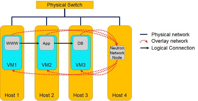
For the most part, this solution works well. However, there is an inherent limitation that affects the overall system performance and scalability:
All cross-subnet traffic hits the Network Node.
 |

In Juno release, a solution to this problem was introduced.
It was called DVR (Distributed Virtual Router).
The main idea was to distribute L3 Agents functionality onto the Compute nodes.
In my next post, I will describe the DVR solution.
Excellent post! Loved those diagrams. Keep up the good work.
ReplyDeleteNice work Eran! ;)
ReplyDeleteTanks for all your work!
ReplyDelete