Sunday, July 26, 2015

Voting for my talks in OpenStack Tokyo 2015

I've submitted several talks to OpenStack Tokyo 2015.
If you find anything here interesting, please vote for it.

(note: you need to have an account in openstack.org to do it)


My submitted talks need your votes:

Dragonflow – L3 Deep dive and hands on lab


OpenVSwitch Scale Performance secrets revealed – and open source solutions


Network high availability by design


Scaling Neutron - Distributing Advanced Services using SDN


Say Hello to 100G OpenStack Networking by Offloading SDN flows using DragonFlow and intelligent NICs (joint talk with Mellanox)


Multi Site Openstack - Deep dive  (joint talk with Midokura)


Thanks for your vote, and see you there.


Tuesday, May 5, 2015

DragonFlow SDN based Distributed Virtual Router for OpenStack Neutron

In my previous posts I presented a PoC implementation of an embedded L3 controller in Neutron that solves the network node bottleneck the SDN way, and overcomes some of the DVR limitations.
In this post I am going to cover the first release of DragonFlow - an SDN based Distributed Virtual Router L3 Service Plugin (aligned with OpenStack Kilo), now an official sub-project of Neutron.
The main purpose of DragonFlow is to simplify the management of the virtual router while improving performance, scale and eliminating single point of failure together with the network node bottleneck.
The DrangonFlow solution is based on separation of the routing control plane from the data plane. This is accomplished by implementing the routing logic in distributed forwarding rules on the virtual switches (called "flows" in OpenFlow terminology). To put this simply, the virtual router is implemented using OpenFlow flows only.
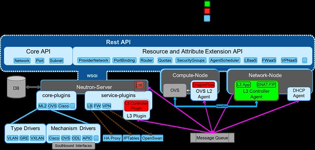
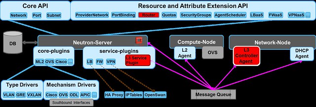
DragonFlow eliminates the use of software stack to act as a virtual router (the Linux network namespaces in the DVR and the legacy L3 architecture), it use purely OVS flow to act as a virtual router. A diagram showing DragonFlow components and overall architecture can be seen here:
DragonFlow High-level Architecture


DragonFlow Features for the Kilo Release:

  • East-West traffic is fully distributed using direct flows, reactively installed upon VM-to-VM first connection.
  • Support for all ML2 type drivers GRE/VXLAN/VLAN
  • Support for centralized shared public network (SNAT) based on the legacy L3 implementation
  • Support for centralized floating IP (DNAT) based on the legacy L3 implementation
  • Support for HA, in case the connection to the Controller is lost, fall back to the legacy L3 implementation until recovery. Reused all the legacy L3 HA. (Controller HA will be supported in the next release).


Key Advantages:

  • Performance improvements for inter-subnet network communication by removing the number of kernel layers (namespaces and their TCP stack overhead)
  • Scalability improvements for inter-subnet network communication by offloading L3 East-West routing from the Network Node to all Compute Nodes
  • Reliability improvements for inter-subnet network communication
  • Simplified virtual routing management, mange only active flows and not all possible 
  • Non Intrusive solution, does not rely on ML2 modification

How it works

  1. On bootstrap the L3 service plugin sends an RPC message to the L2 service plugin, setting the L3  Controller Agent as the controller of the integration bridge.
  2. The Controller queries the OVS  for its port configuration via Openflow, matches the actual ports configured on the OVS to the Neutron tenant networks data model. 
  3. Then, it installs the bootstrap flow pipeline that offloads all L2 traffic and local subnet L3 traffic into the NORMAL pipeline, while sending every unmatched VM-to-VM inter-sunbet traffic to the controller.
DragonFlow L3 Service Bootstrap

The following diagram shows the multi-table OpenFlow pipeline installed onto the OVS integration bridge (br-int) in order to represent the virtual router using flows:

bootstrap flows pipeline

The base table pipe-line is installed proactively on bootstrap while the East-West rules on the L3 Forwarding table are installed reactively on each first VM-to-VM communication.

If you would like to try it yourself, install guide is available here.
To join the development effort: 
My next post will cover the L3 reactive OpenFlow application, and how we install the East-West reactive flows. 

Thursday, January 22, 2015

Neutron DVR The SDN Way

In my previous posts I covered the existing Openstack virtual L3 implementations, from the base centralized implementation to the state of the art solution, DVR, that distributes the load among the computes nodes.

I also summarized the limitations of DVR and hopefully convinced you of the motivation for yet another L3 implementation in Neutron.

Just to quickly recap, the approach for DVR’s design was to take the existing centralized router implementation based on Linux network namespaces and clone it on all compute nodes. This is an evolutionary approach and a reasonable step to take in distributing L3 from which we've learned a lot. However, this solution is far form optimal.

In this post I’m going to present a PoC implementation of an embedded L3 controller in Neutron that solves the same problem (the network node bottleneck) the SDN way, and overcomes some of the DVR limitations.

I chose to start with just the East-West traffic, and leave the North-South for the next step.


I will share some of my ideas for North-South implementation in upcoming posts, as well as links to the Stackforge project.


If you're interested in joining the effort or take the code for a test drive, feel free to email me or leave a comment below.


SDN Controllers are generally perceived as huge pieces of complex code with hundreds of thousands of lines of code that try to handle everything.  It's natural that people would not deem such software to be capable of running "in line".  However, this is not necessarily so.  As I will demonstrate, the basic SDN Controller code can be separated and deployed in a lean and lightweight manner.

It occurred to me that by combining the well-defined abstraction layers already in Neutron (namely the split into br-tun, br-int and br-ext) and a lightweight SDN controller that can be embedded directly into Neutron, it will be possible to solve the network node bottleneck and the L3 high-availability problems in the virtual overlay network in a simple way.

Solution overview 

The proposed method is based on the separation of the routing control plane from the data plane. This is accomplished by implementing the routing logic in distributed forwarding rules on the virtual switches. In OpenFlow these rules are called flows. To put this simply, the virtual router is implemented in using OpenFlow flows. 
The functionality of the virtual routes that we should address in our solution is:


  • L3 routing
  • ARP response for the router ports
  • OAM, like ICMP (ping) and others


L3 Controller embedded in Neutron POC


We decided to create our controller PoC with Openstack design tenets in mind. Specifically the following:

  1. Scalability     - Support thousands of compute nodes
  2. Elasticity       - Keep controllers stateless to allow for dynamic growth 
  3. Performance  - Improve upon DVR
  4. Reliability      - Highly available
  5. Non intrusive - Rely on the existing abstraction and plug-able module

What we intend to prove is:
  • We indeed simplify the DVR flows
  • We reduce resource overhead (e.g. bridges, ports, namespaces)
  • We remove existing bottlenecks (compared to L3Agent and DVR)
  • We improve performance
We've started benchmarking the different models and I'll post results as soon as we have them ready.


Reactive vs. Proactive Mode

SDN defines two modes for managing a switch: reactive and proactive.
In our work, We decided to combine these two modes so that we could benefit from the advantages of both modes (although if you believe the FUD about the reactive mode performance, it is quite possible to enhance it to be purely proactive). To learn more about this mixed mode see my previous blog


The Proactive part

In the solution we install a flow pipeline in the OVS br-int in order to offload the handling of L2 and intra-subnet L3 traffic by forwarding these to the NORMAL path (utilizing the hybrid OpenFlow switch). This means that we reuse the built in mechanisms in Neutron for all L2 traffic (i.e. ML2 remains untouched and fully functional) and for L3 traffic that does not need routing (between IPs in the same tenant + subnet).
In addition we use the OVS OpenFlow extensions in order to install an ARP responder for every virtual router port. This is done to offload ARP responses to the compute nodes instead of replying from the controller.


The Reactive part

Out of the remaining traffic (i.e. inter-subnet L3 traffic) the only traffic that is handled in a reactive mode is the first packet of inter-subnet communications between VMs or traffic addressed directly to the routers' ports.


The Pipeline

Perhaps the most important part of the solution is the OpenFlow pipeline which we install into the integration bridge upon bootstrap.
This is the flow that controls all traffic in the OVS integration bridge (br-int).
The pipeline works in the following manner:


  1. Classify the traffic
  2. Forward to the appropriate element:
    1. If it is ARP, forward to the ARP Responder table
    2. If routing is required (L3), forward to the L3 Forwarding table (which implements a virtual router)
    3. Otherwise, offload to NORMAL path
At the end of this post is a detailed explanation of the pipeline and implementation brief in case you're interested in the gory details.


In my following posts I will cover in detail the code modifications that were required to support the L3 controller as well as publish a performance study comparing the L3 Agent, DVR and the L3 controller for inter subnet traffic.

If you want to try it out, the code plus installation guide  are available here.


Again, if you'd like to join the effort, feel free to get in touch.


detailed explanation of the pipeline

The following diagram shows the multi-table OpenFlow pipeline installed into the OVS integration bridge (br-int) in order to represent the virtual router using flows only:
L3 Flows Pipeline


The following table describes the purpose of each of the pipeline tables:


ID
Table Name
Purpose
0
Metadata &
Dispatch
  • Tag traffic with the appropriate metadata by input port, the value is the segmentation ID
  • Input traffic from the tunnel bridge is offloaded to the NORMAL path
  • All other traffic is sent to the "Classifier" table for classification
40
Classifier
  • All ARP traffic is sent to the ARP responder table
  • All broadcast and multicast traffic is offloaded to the Normal path
  • All L3 traffic is sent to the L3 forwarding table
51
ARP Responder
  • This table handles ARP responses for the virtual router interfaces.
  • The vlan tag is removed from all other traffic and offloaded to the NORMAL path
52
L3 Forwarding
  • This table is used by the Controller to install flows to handle VM to VM inter subnet traffic (detailed explanation below)
  • Traffic destined for a virtual router is sent to the controller (e.g. ping, packet_in, etc)
  • All local subnet traffic is offloaded to the NORMAL path
  • All other traffic is sent to the public network table
53
Public Network
  •  will be described in following blogs


PoC Implementation brief

For the first release, we used the Open vSwitch (OVS), with OpenFlow v1.3 as the southbound protocol, using the RYU project implementation of the protocol stack as a base library.
The PoC support Route API for IPV4 East -West traffic.  
In the current PoC 

implementation, the L3 controller is embedded into  the  L3 service plugin.  

Thursday, January 15, 2015

Common Misconceptions about SDN Controller Management and Scalabilty

Here are a few common misconceptions about SDN controller management and scalability.

#1: Either Proactive mode or Reactive mode

When an SDN controller wants to enforce a set of rules or a policy on a forwarding element, it uses the southbound API, OVSDB, OpFlex, OpenFlow or others. In OpenFlow this process is called flow installation and it can be done using different methods: proactive, reactive or mixed (aka hybrid approach).  


Proactive

During bootstrap, the controller installs all flows and pipelines (multi-table entries) into all the forwarding elements.  The flows must cover all possible scenarios.
Whenever there is a change in the network, the controller removes or installs flows where necessary.


Reactive

When a packet arrives in a switch, a look-up is performed on the flow tables.
If there is no match and the switch is connected to a controller, it will forward the packet (either with or without its payload) to the controller.
In OpenFlow, this is called a PACKET_IN message.

It is also possible to create rules that forward the packet to the controller when matched and we call that...


Mixed Proactive / Reactive

With the mixed approach, you can benefit from the best of both worlds, achieving a balance between dynamic management and performance.

For frequently-used and rarely-modified flows, you install a pipeline and flows proactively.

For unmatched flows, or for flows that you want to handle in-line in your SDN application, you install a flow to forward the packet to the controller.

This mixed approach allows the controller to focus on making real-time dynamic decisions only on the traffic that requires it (reactive), while leaving the heavy-lifting of the majority of the traffic to the real-time forwarding element (proactive).

In addition, with this approach you can avoid over-provisioning the forwarding element with flows that are rare, thus dramatically reducing the number of entries in the flow tables. 

#2: Lack of Scalability and High Availability


In SDN, the control plane (i.e. the SDN Controller) is separated from the data plane (i.e. the Forwarding Elements).

Due to the centralized nature of control in SDN, we now need to support high availability and redundancy of the Control Plane.

In OpenFlow, the Forwarding Element (the Switch) connects to the controller via TCP or via TLS for secure channels.

Up until OpenFlow v1.2, whenever the connection to the controller was lost, the switch would lose the ability to forward PACKET_IN messages to the controller, thus having to drop all unmatched traffic or handle it in the NORMAL switch (only in switches that implemented the dual nature). 

This non-deterministic approach would yield unpredictable network behavior 
while the controller was unavailable.

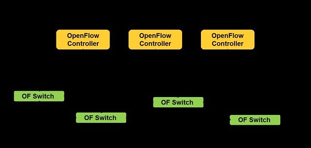
OpenFlow v1.2 introduced the capability of working with multiple controllers.
The Master and Slave modes provide a mechanism for Active-Passive high availability, whereas the Equal mode provides an Active-Active model.

OpenFlow multiple controllers


With the multi-controller capability, we gained the control plane high availability we needed, improved reliability, fast recovery from failure and controller load balancing.

#3: You cannot design SDN Applications for Really Big Scale


Utilizing the two mechanisms I covered - Mixed-Mode and Multi-Controller - is the key to designing really big scale SDN applications.

If you take care to design your application to be stateless (whenever possible) and share nothing (or little) with other controller instances you can benefit from the Reactive mode where any instance can handle any flow.

In my opinion, the best approach for achieving minimal controller response latency and maximal bandwidth while keeping the dynamic allocation of flows, is by using all of these mechanisms together.

When you add to that the OVS OpenFlow extensions and the dual-nature Hybrid OpenFlow capability (which I covered in my previous post), you can really gain a dramatic performance and management boost.


In my next post I will demonstrate how we utilized these design guidelines and capabilities in a prototype for an alternative to Neutron's L3 Distributed Virtual Router.

Tuesday, January 13, 2015

Hybrid OpenFlow Switch


In my last post I summarized the DVR solution and tried to explain the motivation for yet another L3 implementation in Neutron that I am going to present in the coming posts.

This 2-post series is intended to cover basic SDN and OpenFlow mechanisms that we used in the L3 controller:
  • Hybrid OpenFlow Switch 
  • SDN models for managing the forwarding elements (switches)

Hybrid OpenFlow Switch

Hybrid OpenFlow switch was introduced in OpenFlow/1.1. Hybrid switches support both OpenFlow operation pipeline and normal (legacy) Ethernet switching functionality.

The hybrid switch allows forwarding of packets from the OpenFlow
pipeline to the normal pipeline through the NORMAL and FLOOD reserved ports.

The main reason for introducing the hybrid switch was to optimize the handling of operations like MAC learning, where a reactive approach was just not efficient - Doing MAC learning in the OpenFlow controller poses significant cost in terms of network bandwidth and latency and does not scale for large networks.

The NORMAL action comes to the rescue and lets us offload legacy non-OpenFlow pipeline (like MAC learning mechanism, VLAN, ACL, QoS and other base features) to the forwarding element kernel module, which is optimized to handle such operations in near-line-rate.

But what happens when the NORMAL action is used in an OpenFlow flow?

Basically, what happens is that the traffic is redirected to a completely separated processing pipeline. This is illustrated in the diagram below.


OVS Hybrid OpenFlow Switch Pipelines
The OpenFlow pipeline and the Normal Pipeline, each act as a completely isolated switch.

There are, however, some issues with this hybrid approach.
  • NORMAL pipeline is not standardized, so it behaves differently on switches from different vendors - There is a variance in the supported features, and no standard way to configure them
  • NORMAL pipeline does not play well with some OpenFlow actions, for example if the port is tagged for the NORMAL pipeline (using the ovs-vsctrl), you can not tag it using OpenFlow actions and then forward it to the NORMAL path, because it will end-up dropped due to double tagging error.

The Open virtual Switch extensions to OpenFlow were developed to support these extra features using Flows, for example the LEARN action (Open vSwitch extension to OpenFlow) for MAC learning .

In my next post I will cover the SDN models for managing the forwarding elements in reactive, proactive and mix modes.

Thursday, January 8, 2015

Openstack Neutron DVR - Summary

Following my 3-post series about Openstack Juno DVR in detail, this post is a summary of DVR, in my point of view.

In the next post I’m going to present a POC implementation of an embedded L3 controller in Neutron that solves the problem differently. In this post I’d like to explain the motivation for yet another L3 implementation in Neutron.

I believe the L3 Agent drawbacks are pretty clear (centralized bottleneck, limited HA, etc), so in this post I’m going to cover the key benefits and drawbacks of DVR as I see them. So without further ado, let’s start.

Pros


First of all, from a functional point of view, DVR successfully distributed the East-West traffic and the DNAT floating IP, which provided significant offload from the Network node contention. This achieved two key benefits, first is that the failure domains are much smaller (Network node failure only affects SNAT) and the second is scalability due to the distribution of the load on all the compute nodes. 


Cons

The approach for DVR’s design was to take the existing centralized router implementation based on Linux network namespaces and clone it on all compute nodes. This is an evolutionary approach and an obvious step to take in distributing L3 from which we’ve learned a lot from. However, it adds load and complexity in three major areas: Management, Performance and Code.

To explain the technical details I will briefly cover two Linux networking constructs used in the solution for East-West communications:

1. Linux network namespaces (which internally load a complete TCP/IP stack with ARP tables and routing tables)
2. OVS flows

OVS flows were needed in order to block the local ARP, redirect return traffic directly to the VMs and to replace the router ports MAC (which cannot be accomplished reasonably using namespaces alone). On the flip side, OVS flows can easily accomplish everything that DVR uses the namespaces for (in East-West communications) and perhaps more importantly it does so in a more efficient way (avoids the overhead of the extra TCP/IP stack etc). To hint at our solution, flows also allow us to further improve the solution by selectively using a reactive approach where relevant.


Extra Flows Install for DVR
So overall it seems that using the Linux network namespace as a black box to emulate a router is an overkill. This approach makes sense in the centralized solution (L3 Agent) where for each tenant’s virtual router we use a single namespace in the DC, however, in the distributed approach where the number of namespaces in the DC is multiplied by the number of compute nodes this needs to be reevaluated.
If you’re not convinced yet, here is a summary of the implications of using this approach:

Resource consumption and Performance

1. DVR adds an additional namespace as well as virtual ports per router on all compute nodes that host routed VMs. This means additional TCP/IP stacks that each and every cross subnet packet traverses. This adds latency and host CPU consumption.

2. ARP tables on all namespaces in the Compute nodes are proactively pre-populated with all the possible entries. Whenever a VM is started, all compute nodes which have running VMs from the same tenant will be updated to keep these tables up to date (which potentially adds latency to VM start time)

3. Flows and routing rules are proactively installed on all compute nodes.

Management complexity

1. Multiple configuration points that need to be synchronized: namespaces, routing tables, flow tables, ARP tables and IPTables.

2. Namespaces on all compute nodes need to be kept in sync all the time with the tenant’s VM ARP tables and routing information and need to be tracked to handle failures etc.

3. The current DVR implementation does not support a reactive mode (i.e. creating a flow just-in-time), thus all possible flows are created on all hosts, even If they’re never used.

Code Complexity

1. The DVR required cross-component changes due to its multi configuration points: The Neutron server Data Model, ML2 Plugin, L3 Plugin , OVS L2 Agent and the L3 Agent.

2. Using all Linux networking constructs in a single solution (namespaces, flows, linux bridges, etc) requiring code that can manage all of it.

3. The solution is tightly coupled with the overlay manager (ML2) which means that the addition of every new type driver (today only vxlan) requires code additions on all levels (as can be seen by the vlan patches)

In my next post I will present an alternative solution, we evaluated and developed (code available) for distributing the virtual router that attempts to overcome these limitations, using SDN technologies.

Comments, questions and corrections are welcome.

Thursday, January 1, 2015

3 Openstack Neutron Distributed Virtual Router (DVR) - Part 3 of 3

In this post, the last of a 3-post series about Openstack Juno DVR, I go into the North-South SNAT scenario in details.

Up until Juno, all L3 traffic was sent through the network node.  In Juno, DVR was introduced to distribute the load from the network node onto the compute nodes.

The L3 networking in Neutron is divided into 3 main services:
  1. East-West communication: IP traffic between VMs in the data center
  2. Floating IP (aka DNAT): The ability to provide a public IP to a VM, making it directly accessible from public networks (i.e. internet)
  3. Shared IP (aka SNAT): The ability to provide public network access to VMs in the data center using a shared (public) IP address
In my previous posts, I covered how DVR distributes the the East-West L3 traffic and the DNAT North-South.
In this post I finish covering the North-South traffic with the Shared IP (SNAT).

SNAT Shared Gateway  North-South 

The SNAT North-South shared public gateway functionality was not distributed by DVR.  It remains centralized on the Network Node, as you can see in the diagram below.


In order to configure the SNAT namespaces on the Network node, the SNAT-DVR L3 agent is deployed.

An additional private address is assigned in the SNAT namespace for each of the DVR connected subnets, thus providing the centralized SNAT functionality.

Lets follow a communication flow from VM3 in the App network to the public network. 
  1. The packet is forwarded to the DVR namespace via the local DVR default gateway port
  2. If the packet destination is not private, then it is routed to the appropriate default public gateway port (based on the source subnet) on the SNAT namespace 
  3. An OVS flow converts the local VLAN into the App network segmentation ID
  4. The packet is forwarded into the SNAT namespace and NAT-ed using the SNAT public address
Let's look at a concrete example:
[Public Network range]=10.100.100.160/28
[App Network]=192.168.200.0/24
[Shared Public IP (SNAT)]=10.100.100.162
[VM3 private IP]=192.168.200.6

In my next post I will summarize the DVR solution in Openstack Juno.

Questions and comments are welcome.

The configuration files I used to set-up the Openstack  Neutron into DVR mode can be found here.