In this post, the 2nd of a 3-post series about DVR, I go into the North-South DNAT scenario in details.
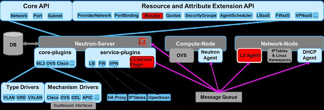
Up until Juno, all L3 traffic was sent through the network node. In Juno, DVR was introduced to distribute the load from the network node onto the compute nodes.The L3 networking in Neutron is divided into 3 main services:
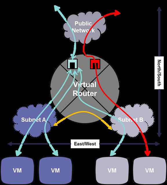
- East-West communication: IP traffic between VMs in the data center
- Floating IP (aka DNAT): The ability to provide a public IP to a VM, making it directly accessible from public networks (i.e. internet)
- Shared IP (aka SNAT): The ability to provide public network access to VMs in the data center using a shared (public) IP address
In this post I am going to begin covering the North-South traffic starting with Floating IP (DNAT).
DNAT Floating IP North-South
In order to support Juno's DVR local handling of floating IP DNAT traffic in the compute nodes, we now require an additional physical port that connects to the external network, on each compute node.The Floating IP functionality enable direct access from the public network (e.g. Internet) to a VM.
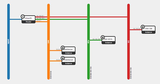
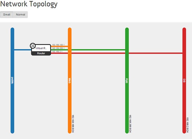
Let's follow the example below, where we will assign a floating IP to the web servers.
When we associate a VM with a floating IP, the following actions take place:
- The fip-<netid> namespace is created on the local compute node (if it does not yet exist)
- A new port rfp-<portid> is created on the qrouter-<routerid> namespace (if it does not yet exist
- The rfp port on the qrouter namespace is assigned the associated floating IP address
- The fbr port on the fip namespace is created and linked via point-to-point network to the rfp port of the qrouter namespace
- The fip namespace gateway port fg-<portid> is assigned an additional address from the public network range (the floating IP range)
- The fg-<portid> is configured as a Proxy ARP
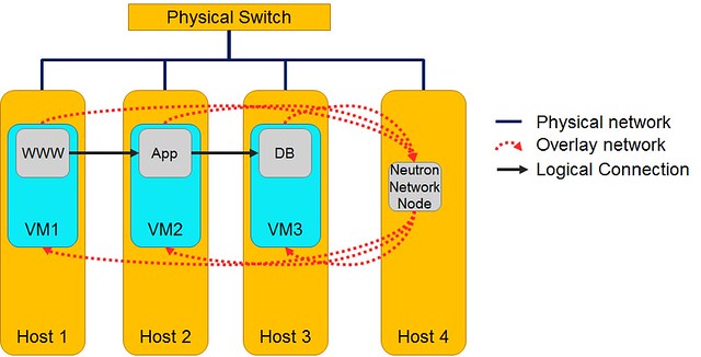
Now, lets take a closer look at VM4 (one of the web servers).
In the diagram below, the red dashed line shows the outbound network traffic flow from VM4 to the public network.

The flow goes through 5 steps:
- The originating VM sends a packet via default gateway and the integration bridge forwards the traffic to the local DVR gateway port (qr-<portid>).
- DVR routes the packet using the routing table to the rfp-<portid> port
- The packet is applied NAT rule using IPTables, changing the source-IP of VM4 to the assigned floating IP, and then it is sent through the rfp-<portid> port, which connects to the fip namespace via point-to-point network (e.g. 169.254.31.28/31)
- The packet is received on the fbr-<portid> port in the fip namespace and then routed outside through the fg-<portid> port
[Public Network range]=10.100.100.160/28
[Web Network]=10.0.0.0/24
[VM4 floating IP]=10.100.100.163
[VM4 private IP]=10.0.0.6
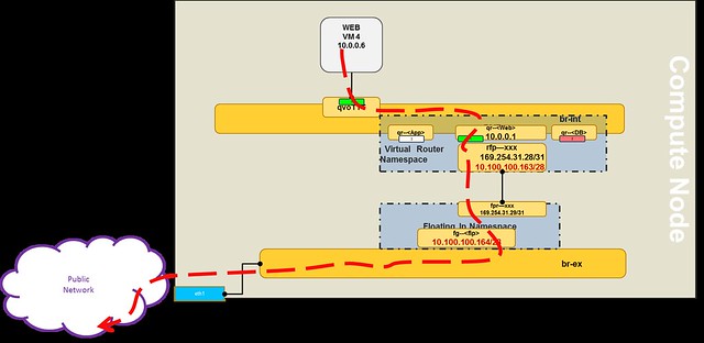
As you can see in the diagram, routing consumes an additional IP from the public range per compute node (e.g. 10.100.100.164).
The reverse flow will go in the same route, the fg-<portid> act as a proxy ARP for the DVR namespace.
In the next post, I will go into the North-South scenario using Shared IP (SNAT).
Please feel free to leave comments, questions and corrections.
Please feel free to leave comments, questions and corrections.


